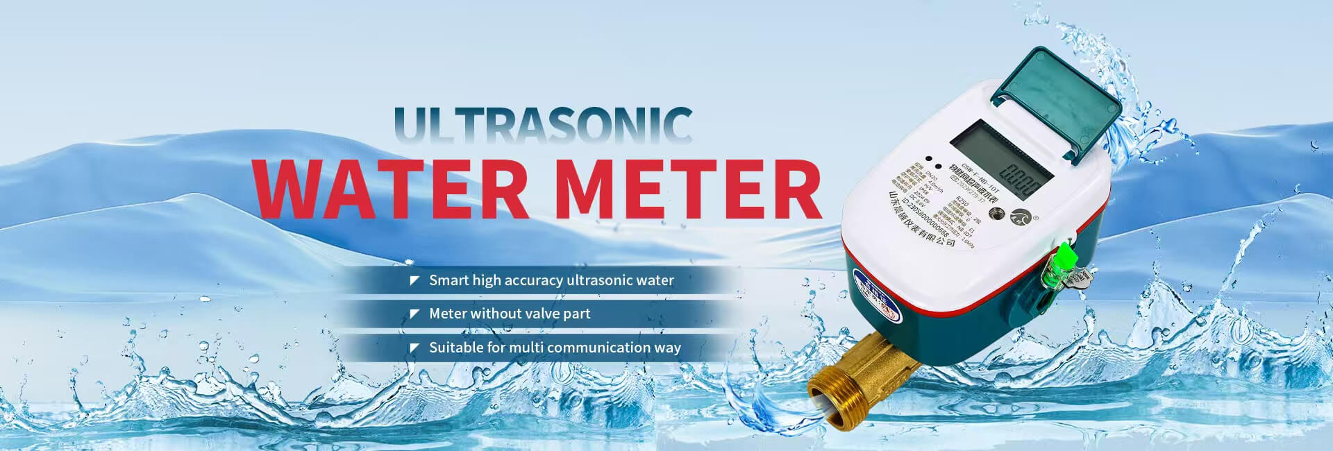


A pulse output water meter sends an electrical event for a defined volume of water. A building management system, or BMS, counts those events and converts them into consumption. To make that total useful, the meter output and receiving input must agree on pulse value, electrical characteristics and timing, with a recorded starting value for comparison.
Begin with the intended result. Monthly consumption needs a dependable accumulated total; short-interval monitoring also needs enough resolution to show small changes. A meter can serve the first purpose while producing data that is too coarse for the second.

A pulse-ready register may need a separate module. An electronic meter may use pulses internally without exposing a terminal for external equipment. Obtain the exact output specification and wiring diagram for the ordered version, including any module that enables the connection.
For larger conductive-water applications, electromagnetic flowmeters with pulse and Modbus output options provide one route to evaluate. Confirm the selected converter, terminal functions and electrical limits before matching it to a controller. A list of available outputs does not establish that every option is installed or compatible with every BMS input.
Chenshuo’s XT815-M uses mechanical pulse measurement. That description identifies the measuring arrangement; it is not sufficient evidence of an accessible BMS pulse connection. Ask specifically for an external output and its interface document if that is what the project requires.
Pulse value, sometimes called pulse weight, is the volume represented by one event. At 10 litres per pulse, 240 counted pulses represent 2,400 litres, or 2.4 cubic metres. This is a hypothetical conversion example, not a specification for a particular meter.
Volume = pulse count × volume per pulse.
Some controllers ask for pulses per unit instead. These values are reciprocals only when the volume unit is the same. Ten litres per pulse equals 0.1 pulse per litre, or 100 pulses per cubic metre. Entering 10 into a field expecting pulses per litre creates a very different result.
Record the unit beside every setting. Compare the module label, controller configuration and displayed BMS engineering unit before running water. A screen showing cubic metres can conceal a wrong conversion if nobody checks the arithmetic against the raw count.
A smaller volume per pulse gives finer count resolution, provided the receiving input can capture the resulting events. A coarser output may suit a cumulative consumption total but can produce long gaps between pulses at low demand. Those gaps should not automatically be interpreted as no water use.
For a hypothetical steady flow of 5 litres per minute, a 10-litre pulse arrives about every two minutes once the cycle is established. A 1-litre pulse arrives about every twelve seconds. This describes output resolution, not the meter’s low-flow accuracy. Verify the measuring range independently when assessing small-flow monitoring.
A reed-switch output commonly behaves as a potential-free contact. An open-collector output is an electronic switching arrangement that requires a compatible input circuit and correct polarity. Active outputs introduce another set of voltage and current requirements. Never infer the connection from wire colour or wire count alone.
| Item to match | What to request | Why it matters |
| Output and input types | Circuit type and approved connection diagram | Prevents an electrically incompatible pairing |
| Voltage and current | Output limits and input sensing requirements | Avoids damage or unreliable switching |
| Pulse timing | Minimum on-time, off-time and maximum frequency | Prevents pulses being missed at higher flow |
| Counting rule | Selected edge or complete-pulse detection | Prevents duplicate counting of one event |
| Cable arrangement | Length, shielding, joints and routing instructions | Limits interference and installation faults |
A pulse output is not automatically an S0 interface, and a pulse wire cannot be connected directly to an RS485 communication terminal. Use a compatible pulse counter or interface module where required. Have a qualified installer follow both manufacturers’ diagrams, including isolation and grounding requirements.
Contact bounce can create several rapid transitions from one reed operation. Debounce filtering helps reject these, but an excessive filter can also reject legitimate short pulses. Select the setting from the output timing and input requirements, then verify it under the expected operating conditions.
The pulse value must work at the upper end of the flow profile as well as the lower end. When selecting a water meter for the expected flow conditions, carry those same conditions into the counter specification. For flow Q in litres per minute and pulse value Vp in litres per pulse:
Pulse frequency in hertz = Q ÷ (60 × Vp).
At a hypothetical peak of 120 litres per minute and 1 litre per pulse, the output rate is 2 Hz. There are 0.5 seconds between pulse starts. A 0.01-litre pulse value at the same flow would require 200 Hz, which may exceed the output or counter capability.
Check both devices’ maximum frequency and the required on-time and off-time. Also confirm that the controller uses a counter input capable of capturing the pulses; polling an ordinary on/off point slowly may miss events. Follow the documented limits with suitable engineering margin instead of assuming that a finer pulse value is always better.
A basic pulse count records increments after counting begins. To display a value corresponding to the local register, photograph that register, record the time and assign a starting offset. If the purpose is consumption since installation, starting at zero may be appropriate, provided the display is labelled clearly.
Ask how the selected output treats reverse flow. Depending on the design, it may count without direction, compensate for reverse volume or provide a separate signal. The BMS calculation must match that behaviour. Do not assume a single pulse channel tells the controller which way water moved.
If the project needs meter identity, diagnostic status or an absolute reading, evaluate a documented digital interface as well. The distinction between local measurement and connected meter functions matters here: an added counter does not automatically provide the information or controls of a fully integrated meter system.
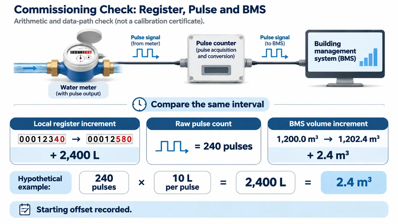
Test the register, counter and application together before accepting a batch. Record the module settings and controller input configuration so another installer can reproduce the result. Keep meter identity and BMS point name in the same record.
Allow for pulse quantization and different update times when interpreting small discrepancies. A short draw can begin partway through a pulse cycle, leaving a residual volume that appears in the next pulse. Define the comparison tolerance from the pulse value, display resolution and test method before declaring a counting fault.
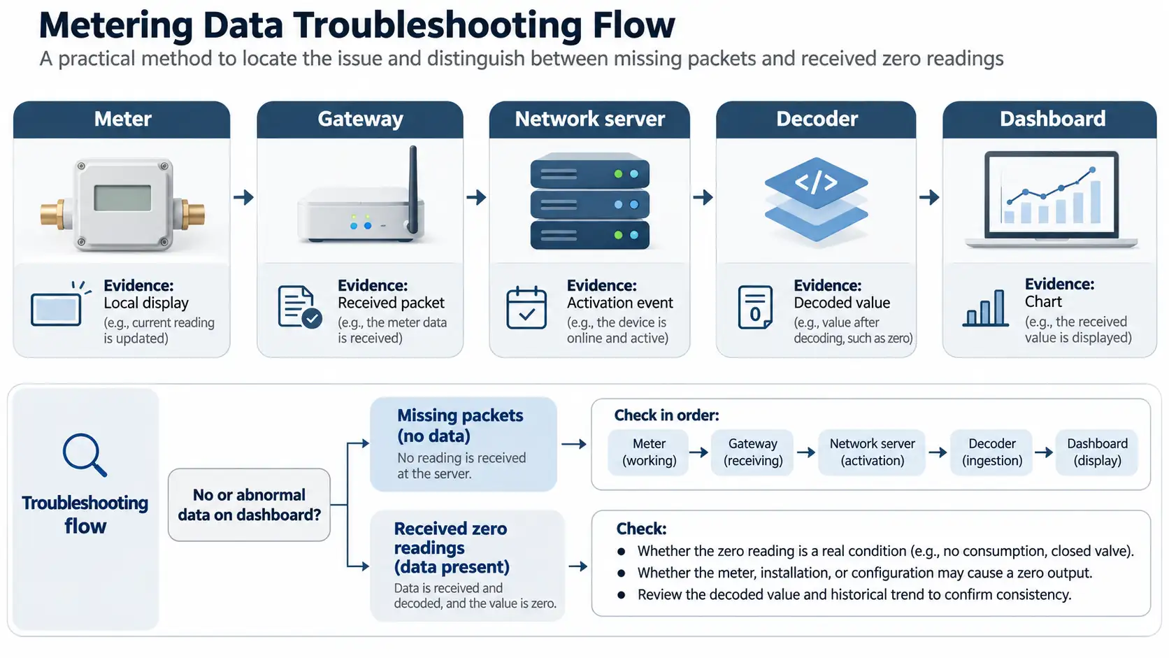
If the count is correct but the displayed volume is wrong, inspect scaling. If only the high-flow test fails, inspect frequency limits, timing and filtering. If a restart changes the total, examine storage and initialization. A counter may retain accumulated volume during a network interruption while detailed interval history remains incomplete; confirm both behaviours separately.
No. It gives finer output resolution but produces more pulses at the same flow. Check the meter output, counter capacity and monitoring purpose before choosing the smaller value.
It transfers measurement increments to another device. It does not correct an unsuitable measuring range, wear or installation error. Counting and scaling can also introduce discrepancies that require separate checks.
No. Compatibility depends on the register and the approved accessory. Confirm the meter model and module part number; a similar-looking register is not sufficient evidence of compatibility.
Check the starting offset, units, pulse value, timing, missed or extra pulses and reverse-flow behaviour. Compare increments over the same period before comparing absolute totals established at different starting points.
It may support billing when the complete arrangement meets the applicable metering and billing requirements. Verify approval, traceability and the accepted register or data source. A working BMS connection alone does not establish billing compliance.
Send Chenshuo the meter duty, required pulse value, controller input specification and commissioning criteria to request an interface and meter selection review. Ask for confirmation of the exact output configuration before ordering the meter and counter together.
 Adresse: Xiao'anzi Industrial Park, Baishabu Town, Lanshan District, Linyi City, Province du Shandong
 Appelez-nous maintenant:+86 15562945993
 E-mail:info@sdchenshuo.cn


Shandong Chenshuo Instrument Co., Ltd.