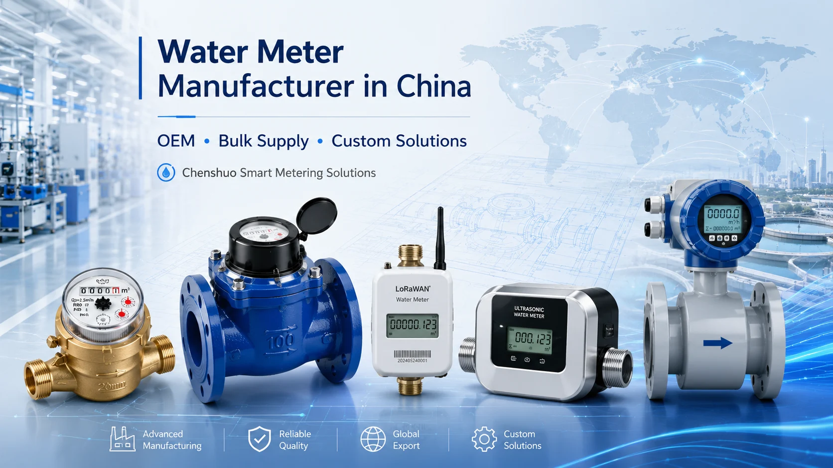
When you notice sudden drops in flow accuracy, the issue often hides right in the piping structure. Setting up measuring devices correctly takes serious field experience, and a tiny layout mistake easily destroys data reliability. That is exactly where di Chenshuo steps in as an industry expert. For years, this manufacturer has solved complex fluid tracking problems for industrial facilities, focusing heavily on smart metering solutions. Getting the physical setup right is half the battle, and having a reliable hardware partner makes the rest much easier. Now, let us dig into the exact reasons why pipe configuration matters so much for acoustic measurement and how to fix common layout errors.
Finding out that your new flow device reports the wrong numbers is frustrating. The sensors might work perfectly, but the physical environment around them ruins the data. Let us look at the specific physical barriers that disrupt the acoustic signals in a typical pipeline.
When water flows through a 90-degree elbow or a sharp T-junction, it does not just turn smoothly. The fluid crashes into the outer wall and creates a swirling motion. This turbulence totally distorts the velocity profile. Acoustic beams calculate volume by measuring the time difference of sound traveling with and against the flow. If the water inside spins wildly, the sound waves hit different speed zones, giving you a completely wrong average velocity.
Every flow device needs water to move in a calm, uniform pattern. To get this calm state, you need enough straight pipe before the water hits the sensors. Skipping this step is a classic mistake. Sometimes contractors squeeze a meter into a tight space right after a valve to save room. This ruins the baseline. Without the required straight section, the fluid profile stays distorted, and the device simply cannot track the flow correctly.
Air pockets are absolute signal killers. Gases dissolve in water during production or enter through tiny leaks during pipe construction. Compressible gas expands and contracts with pressure changes, and more importantly, it blocks sound waves. When an acoustic pulse hits a bubble, it scatters. The receiver on the other side gets a weak or broken signal, which directly leads to data drops or wild reading spikes.
Knowing the problems is just half the battle. Setting up the piping grid correctly prevents these measurement disasters from happening in the first place. You have to follow a few core physical rules to get the best out of your investment.
Standard guidelines dictate clear rules for straight pipe runs. Usually, you need a straight section of at least 10 times the pipe diameter upstream and 5 times the diameter downstream. For example, a 15mm unit needs 150mm of straight pipe at the inlet. This physical distance gives the swirling water enough time to calm down and form a stable flow shape. Keeping this exact distance is tough in crowded mechanical rooms, but it remains a non-negotiable rule for precise tracking.
These devices calculate volume by multiplying the flow velocity by the cross-sectional area of the pipe. This mathematical formula assumes the pipe is entirely full of water. If the pipe only runs half full, the device still calculates as if it were completely full, inflating your numbers massively. Always install the device at a low point in the system to keep the pipe fully packed with fluid.
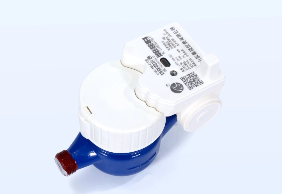
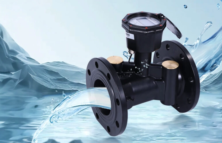
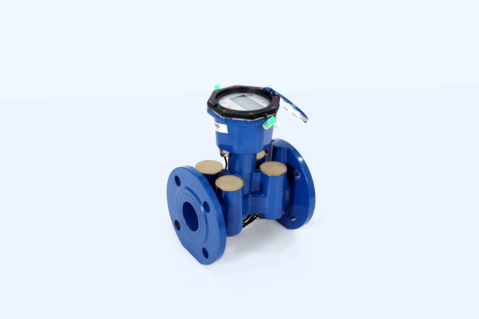
Sometimes you just do not have the luxury of long straight pipes. Advanced designs tackle this spatial limit head-on. A solid example is the Contatore d'acqua ad ultrasuoni-DN80. This specific unit uses tuned internal flow channels and highly sensitive transducers that tolerate slightly less-than-ideal straight runs. It delivers highly accurate data even when the physical layout gets a bit cramped, saving you from expensive pipe reconstructions.
Industrial plants are crowded places full of massive equipment, twisting pipes, and heavy vibrations. This chaotic environment creates several traps for flow measurement. You need to identify these layout mistakes early to protect your data integrity.
Pumps are aggressive machines. They smash water forward, creating intense pressure waves and violent swirls. Placing a measurement device right after a discharge nozzle is asking for trouble. The kinetic energy generated by the pump makes it impossible to get a clean acoustic reading. You must place the sensors far away from any active pumping station to let the fluid dynamics settle down.
Gravity is not always your friend here. When water flows straight down a vertical pipe, it often accelerates faster than the pipe can fill. This creates a vacuum or a partially empty section. As discussed earlier, a partially empty pipe ruins the volume calculation. Always place the measuring section on a horizontal line or an upward vertical climb where gravity naturally keeps the pipe fully packed.
Valves control flow by physically blocking the water path. A partially closed gate valve or butterfly valve tears the fluid stream into chaotic jets. If you place a valve directly upstream of your sensors, you feed them garbage data. The best practice is to always place control valves downstream. This way, the water passes through the measuring zone cleanly before the valve disrupts it.
Real-world piping rarely looks like the perfect diagrams in engineering textbooks. You will often deal with tight corners, aging infrastructure, and massive flow volumes. Thankfully, the right hardware choices can overcome these environmental limits.
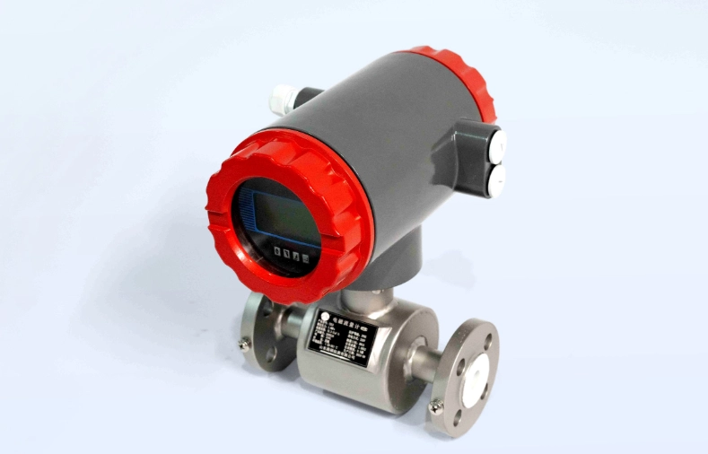
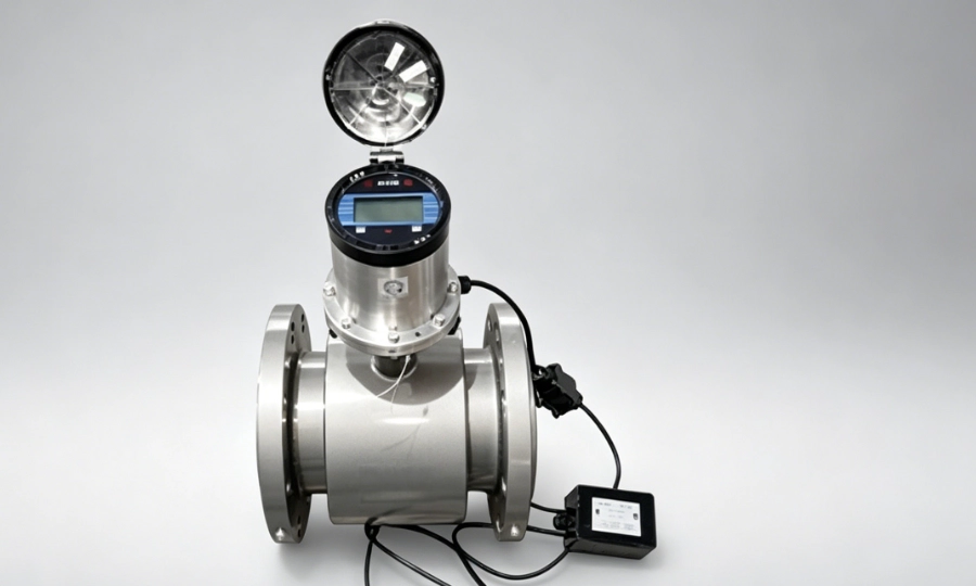
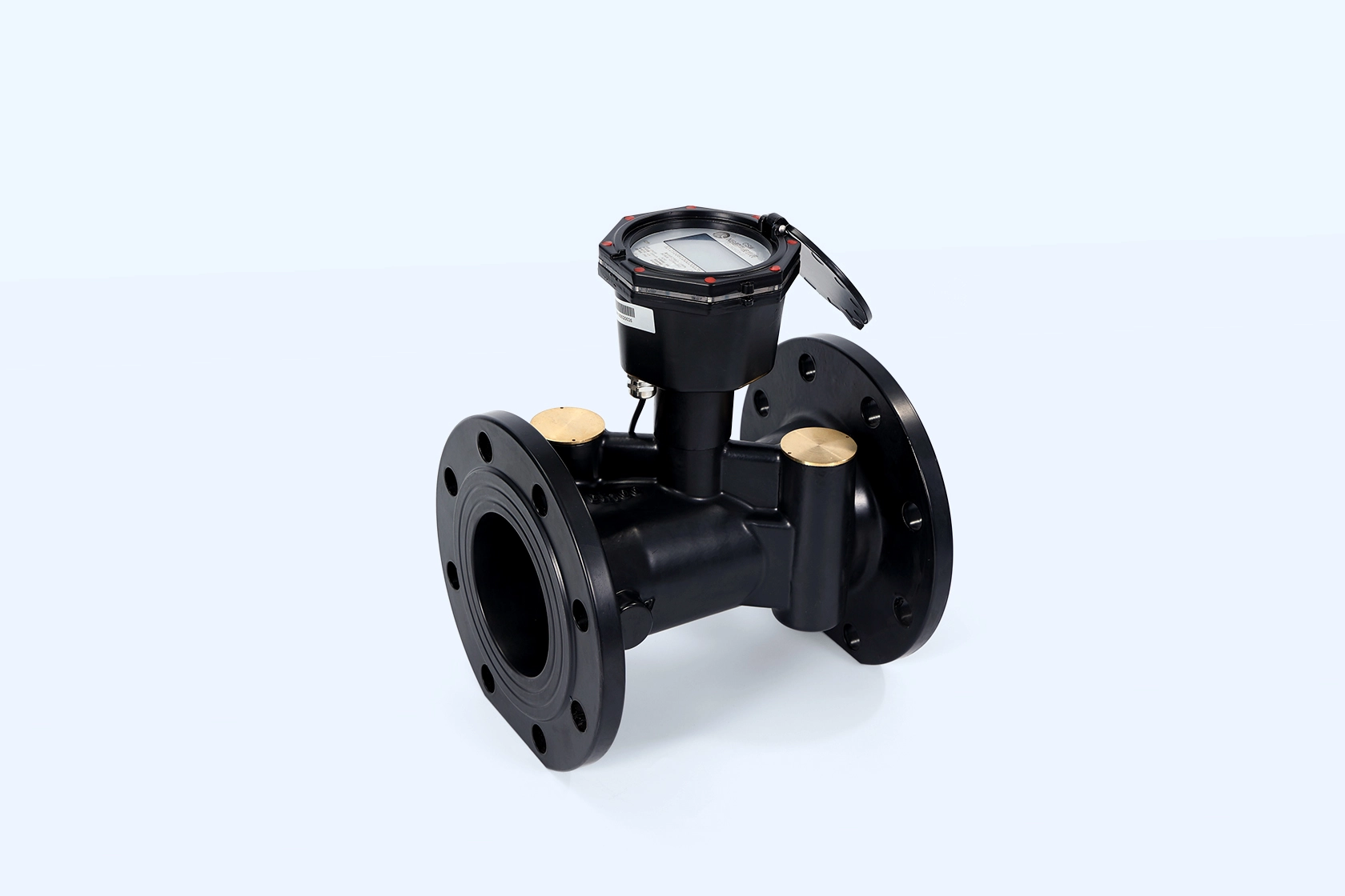
When dealing with large-scale industrial water supply, the volume and pressure stress test every piece of hardware. Mechanical wear becomes a huge issue under long-term high flow, causing traditional meters to slow down and lose accuracy. To handle this, the Contatore d'acqua ad ultrasuoni-DN100 steps up perfectly. It has no moving parts to wear out, offers a massive measurement range, and effectively processes high-volume tracking without the constant breakdowns seen in older mechanical setups.
You do not have to guess if these solutions actually work in the dirt and grime of a real factory. The Chenshuo Case Center documents numerous field deployments where severe pipe layout issues were resolved. Looking at past projects gives you a practical blueprint for tackling your own specific site challenges, proving that a smart layout combined with robust hardware always wins.
If you absolutely cannot find enough straight pipe length, flow conditioners offer a mechanical shortcut. These metal inserts go inside the pipe and force the chaotic swirling water into straight, parallel streams. While they do add a small amount of pressure loss, they drastically reduce the required upstream distance, letting you get accurate numbers in very cramped utility rooms.
Upgrading your water tracking infrastructure is a significant industrial investment. You need hardware that lasts and a team that actually knows how fluid behaves in real pipes. Finding a solid manufacturing partner takes the guesswork out of your layout planning.
Building sensitive acoustic equipment requires precise engineering and strict quality control. A factory with a long track record knows how to seal electronics against moisture and protect transducers from temperature shocks. Browsing the About Us details shows a deep manufacturing experience, meaning you get a unit that survives harsh industrial realities rather than failing after a few months.
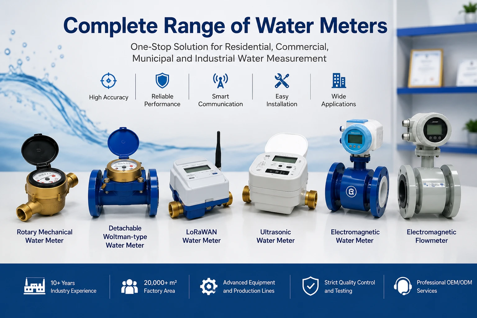
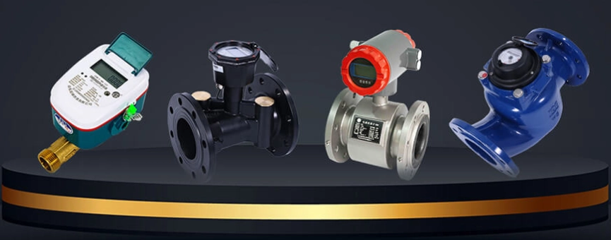
Different sites need different tools. A residential feed requires low-flow sensitivity, while a large industrial plant needs high overload capacity. Having access to a broad catalog means you can pick the exact tool for the job. You get hardware tailored to your specific pressure and diameter constraints, rather than forcing a standard unit into a scenario it was never built to handle.
Sometimes the piping layout is so weird that standard rules do not apply. This is when you need to talk to actual engineers. Getting customized advice on where to cut the pipe, how to angle the sensors, and how to avoid pump noise saves you from costly installation mistakes down the road. Just jump to the Contatto section to get expert eyes on your specific blueprint.
Q1: What is the minimum straight pipe length required for accurate measurement?
A: You generally need a straight run of at least 10 times the pipe diameter upstream and 5 times the diameter downstream to maintain a stable flow profile.
Q2: Why does air in the pipeline cause data errors?
A: Gas is highly compressible and blocks acoustic waves. When sound hits an air pocket, the signal scatters, which leads to missing or wildly inaccurate flow data.
Q3: Can these devices be installed vertically?
A: Yes, they can be installed vertically, but the water must flow upwards. Downward flow often causes the pipe to be partially empty, which ruins the volume calculation.
Q4: Do these acoustic devices cause pressure drops in the system?
A: No, because they have a smooth measuring tube with no moving parts or internal filters blocking the water path, the pressure loss is practically zero.
Q5: How does the lack of moving parts benefit industrial users?
A: Without spinning impellers or gears, there is no mechanical wear and tear, even under high-flow conditions. This drastically extends the service life and reduces maintenance costs.
 Indirizzo: Xiao'anzi Industrial Park, Baishabu Town, Lanshan District, Linyi City, Provincia di Shandong
 Chiamaci ora:+86 15562945993
 E-mail: sales2@sd-chenshuo.com


Shandong Chenshuo Instrument Co., Ltd.