In large-scale facilities such as factories, hospitals, hotels, and commercial complexes, pressure loss in water distribution systems increases energy consumption, accelerates pump wear, and reduces overall efficiency. Excessive friction and head loss force pumps to operate at higher capacities, which raises electricity costs and shortens equipment lifespan. Smart selection of components, combined with proper system design, keeps pressure drop low while maintaining accurate metering and reliable flow.
Pressure loss is the accumulation of friction losses from pipes, fittings, valves and metering devices, particularly in large systems with large total flow rates. Although pressure loss due to individual components may be relatively small in large facilities, it can add up quickly when dealing with long runs and many branches.
The largest proportion of friction loss is due to turbulent flow in undersized piping, pipe wall surface roughness, the large number of elbows and valves, and meters. High velocity and sharp changes in piping direction result in significant energy loss as calculated by the Darcy-Weisbach equation.
Higher pressure drop results in higher pump power which translates into higher electricity costs. Continuous overloading can lead to premature bearing and impeller failure and resulting in more maintenance and unexpected down time.
Look for low end user pressure, low flow rates at remote fixtures, short cycle rates and excessive energy consumption or erratic meter readings in areas of uniform demand.
Proper pipe sizing and routing are the keys to achieving a low loss system. Over sizing pipes can lead to low velocity and high friction loss and conversely proper routing will help to minimize excessive bends and turns.
Choose pipe diameter such that velocity in the main line does not exceed 2–2.5 m/s. Increasing pipe diameter decreases pressure drop, especially in high velocity distribution pipes such as common header to off-take pipes.
Shorter runs and less involved curves reduce friction length. Minimize the use of ninety-degree bends and instead employ sweeps or flexible tracing through the circuit.
All fittings add equal length and cap acity. Connect the least number of fittings necessary. Use long radius elbows. Use only the minimum number of isolation valves necessary to allow for easy system modification.
Most water meters impose a certain pressure drop, typically in the main water line or a sub-metered offshoot. Choosing low pressure drop designs will help to maximize system head.
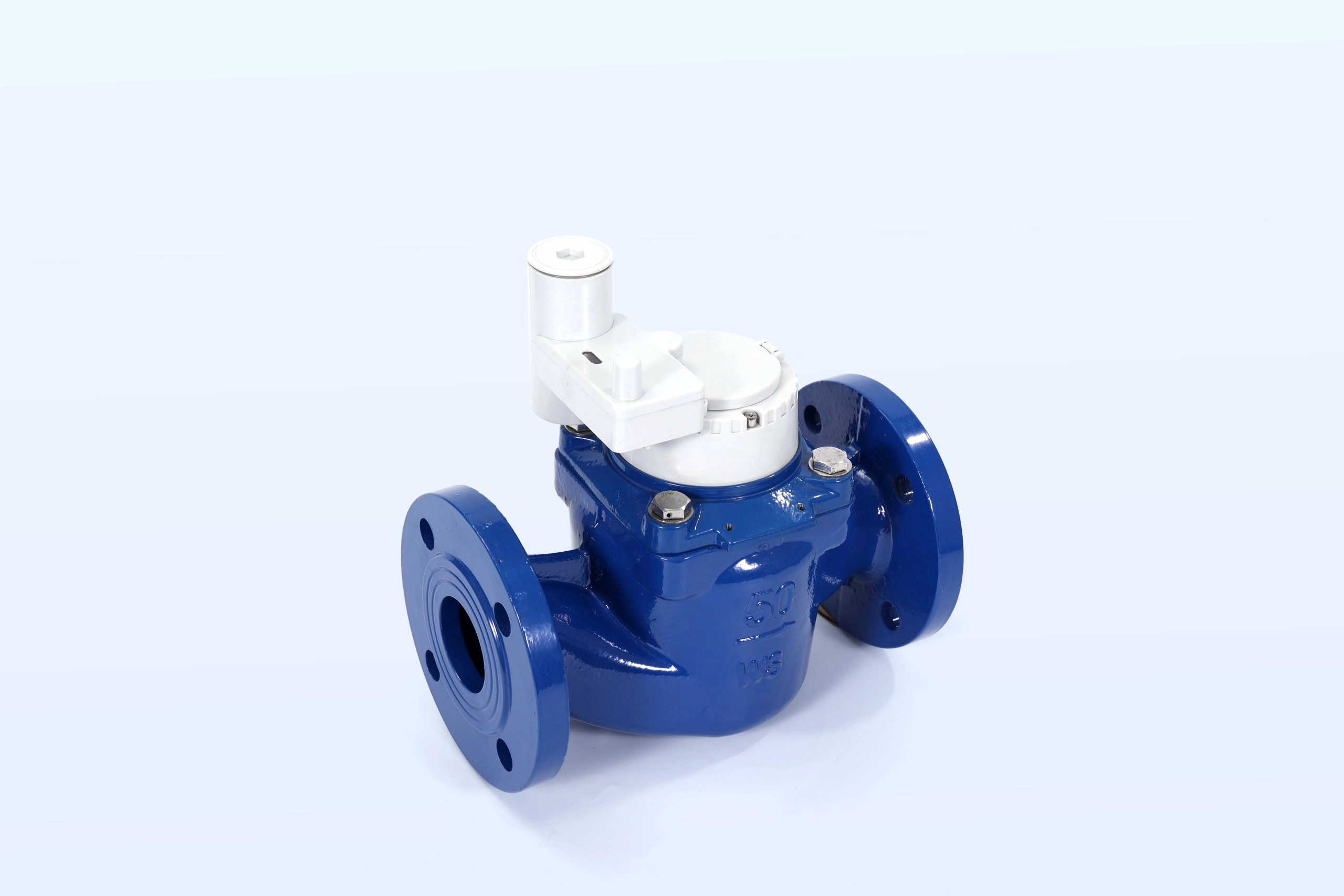
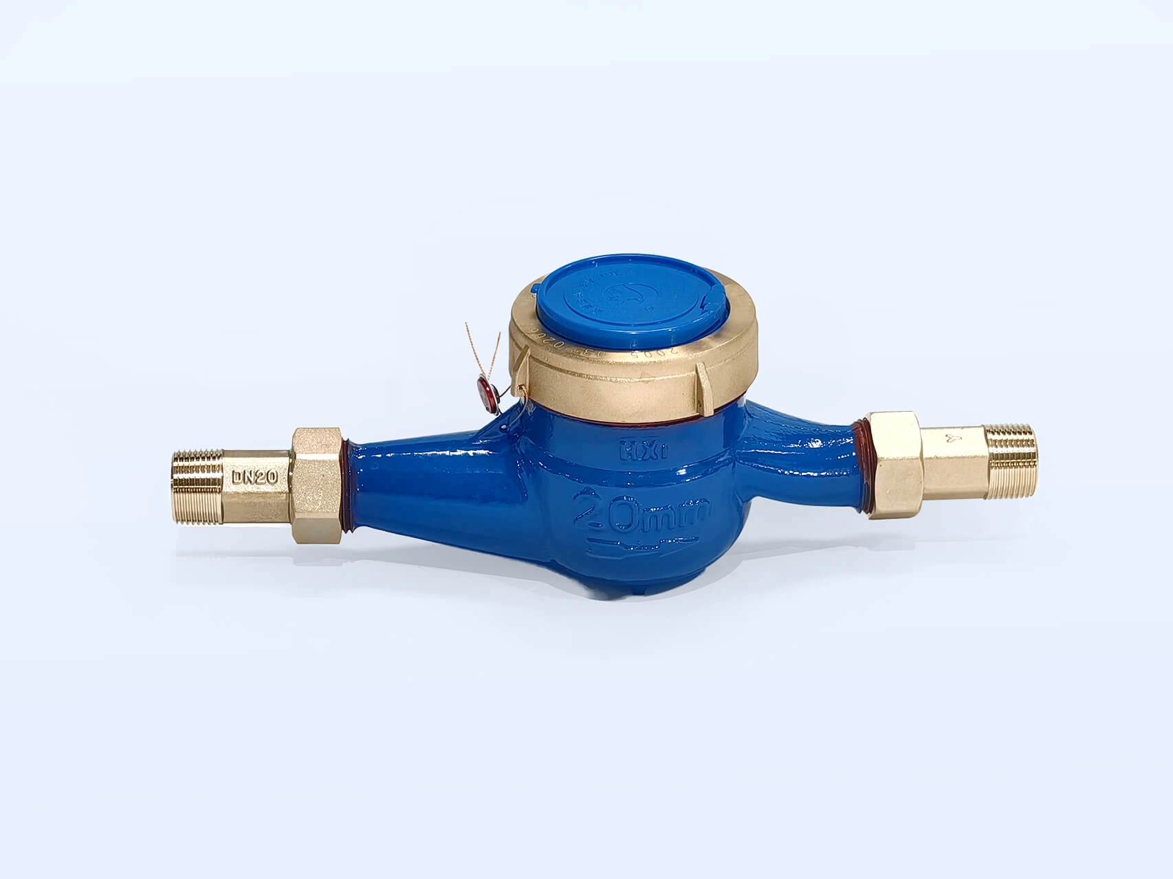
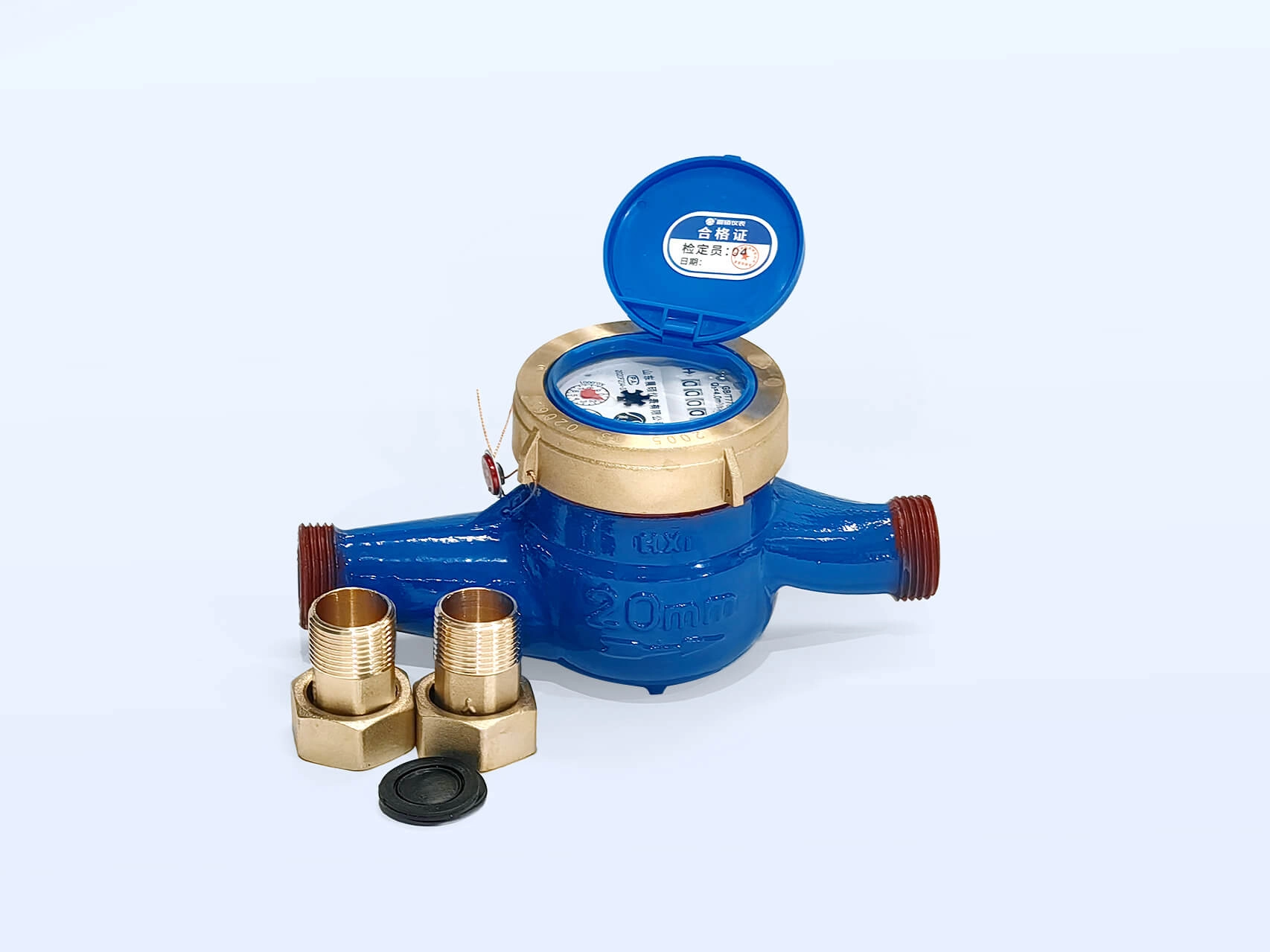
Mechanical meters are designed to operate with a minimum head loss at the nominal flow condition and measure the pressure at the discharge end. In case of rotary type meters the pressure drop at the discharge end is limited to about 0.063 MPa or less at normal operating conditions.
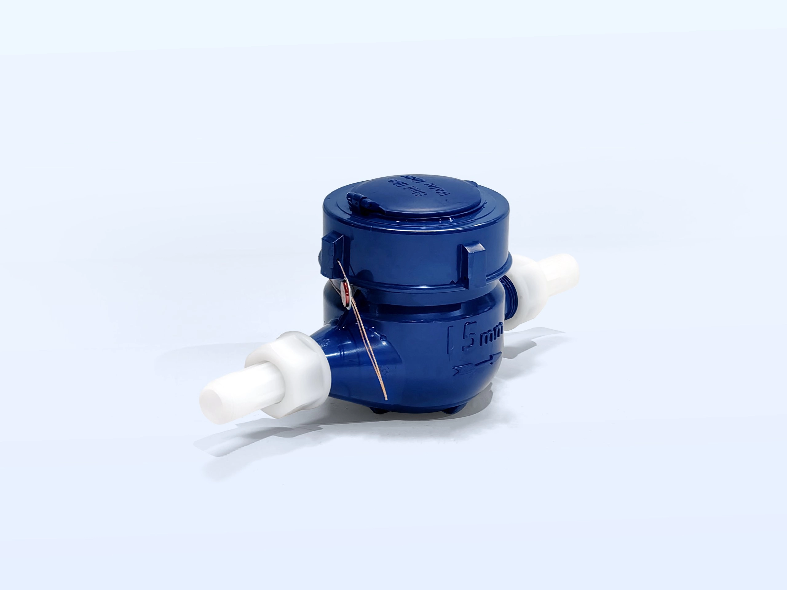
Our bodies are constructed from brass alloy or engineering plastic in order to provide smooth flowing internal conductivities and reduce turbulence loss. Brass alloy and engineering plastic materials also have excellent corrosion and scale resistance, thus ensuring minimal loss over the life of the product.
These effects can be avoided by using a meter of adequate size. Too large an meter results in higher low flows of measurement error, while too small an meter results in unacceptably large heads. For an optimum low loss meter performance, the meter should be sized so that the meter operates closest to the median discharge (Q₃) value. Examples of meters that provide very low loss for indoor use in facility applications are Rotary Mechanical Water Meter LXS-201bas, Rotary mechanical water meter LXS-15 BRASS, Rotary Mechanical Water Meter LXS-15ABS.
This principle links the active control principles with passive design choices. A pressure-balancing control handles excess pressure at the most downstream points of the system and also corrects for pressure drops.
Place PRVs at zone inlets or building entries to maintain consistent downstream pressure. This approach limits excess head in low-demand periods and protects sensitive equipment.
Divide the network into district metered areas with dedicated monitoring. Independent pressure adjustment in each zone reduces overall system pressure and localized losses.
VFD Pumps Vary Speed Based on Pressure Signal Varying speed based on real time pressure will match the pump output to the demand, thus eliminating the costly and unnecessary high head condition, at the same time, reducing the unnecessary power consumption.
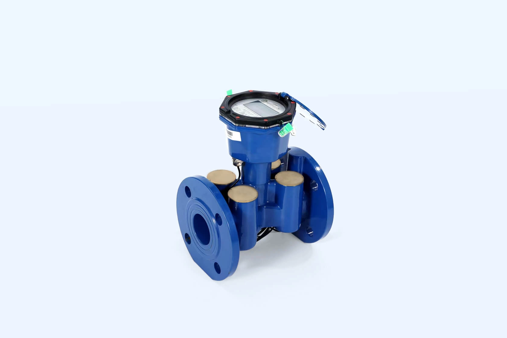
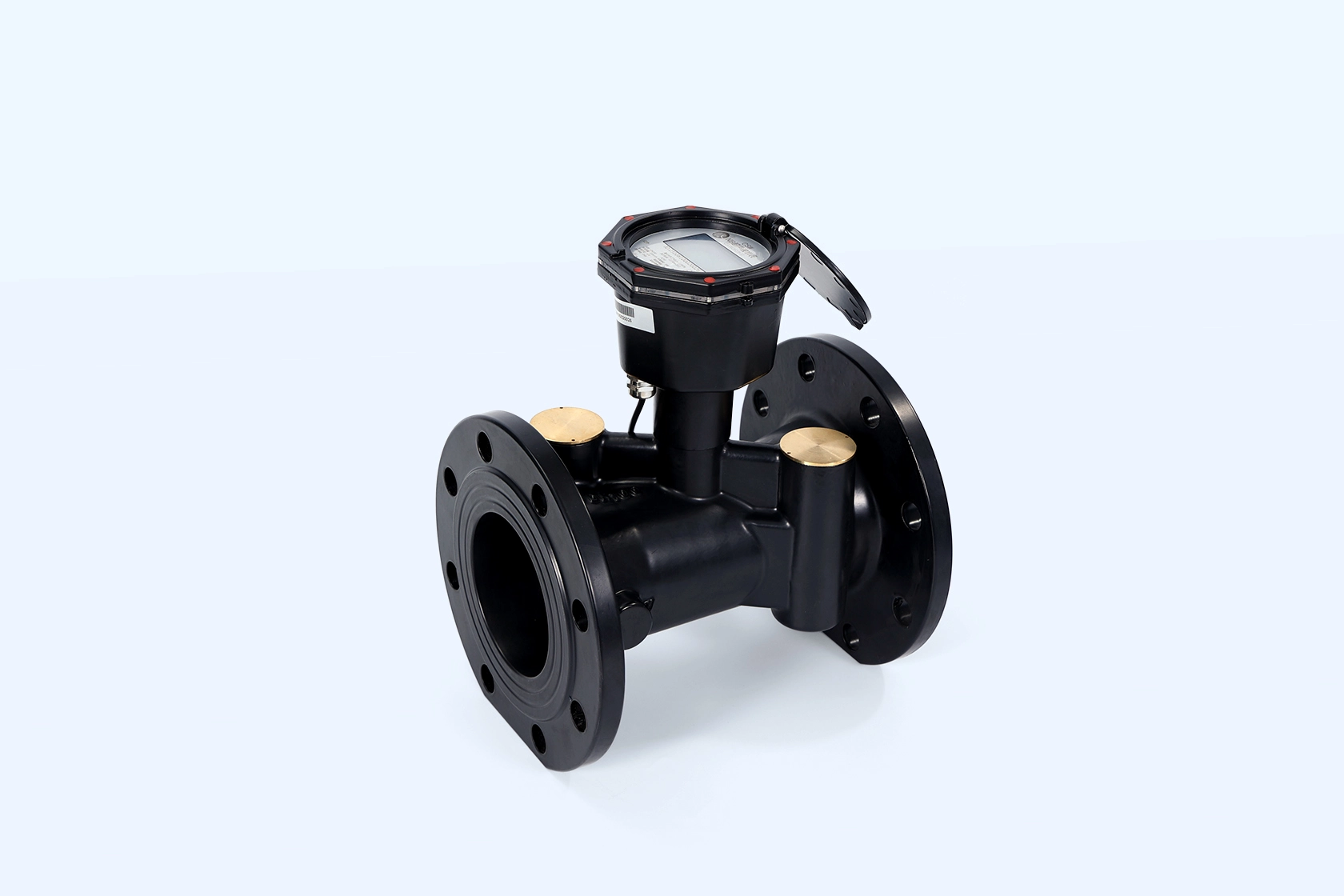
A proper balance between accuracy and pressure loss has to be achieved for a facility that needs to utilize the metering solutions. Чэньшуо‘s rotary mechanical series meters own stable measurement performance and low pressure loss, which can meet the requirements of master pipelines of large-scale projects and thus achieve long-term stable operation and cost reduction.
Global projects choose Chenshuo for high precision, long lifetime and strict compliance with international standards, while based on a large amount of patents and strict testing.
Class 2 accuracy, low starting flow and pressure loss ≤0.063 MPa at permanent flow. Ideal for facility sub-metering and main lines.
Get in touch to discuss the details of your application. Choosing the correct system configuration will help maximize pressure and performance.
Q1: What is the major contributor to pressure loss in a facility water system?
A: Friction from undersized pipes, excessive fittings, sharp elbows, and restricting meters contributes the most pressure loss in a facility water system. Especially on long runs of distribution.
Q2: What head retention can be expected from low pressure loss water meters?
A: Meters with a pressure loss of 0.063 MPa or less at typical flow rates will retain head better than higher pressure loss meters and will therefore contribute to a considerable saving of energy in pumps for larger district piping systems.
Q3: Why match the water meter size to the anticipated flow rate?
A: To ensure the meter operates within its design parameters and to minimize loss of head due to undersized metering as well as to prevent poor low flow measurement due to oversized metering.
Q4 Where should pressure-reducing valves be be added to a facility system?
A: Add PRVs to the system at zone entries or high-pressure inlets to provide sufficient pressure to all points in a zone or branch, to protect the system from over-pressurization, and to make up losses that occur elsewhere in the system.
Q5: How do variable speed pumps help minimize pressure loss?
A: VFD pumps constantly adjust their output based on current demand and pressure, thereby eliminating long periods of constant high-head run time and excess energy consumption throughout the entire system.
 Адрес: Индустриальный парк Сяо'анзи, город Байшабу, район Ланшан, город Лини, провинция Шаньдун
 Позвони нам сейчас:+86 15562945993
 Электронная почта: ivy@sdchenshuo.cn


Shandong Chenshuo Instrument Co., Ltd.